ZHCSO96B June 2021 – June 2022 DAC12DL3200
PRODUCTION DATA
- 1 特性
- 2 應用
- 3 說明
- 4 Revision History
- 5 Pin Configuration and Functions
-
6 Specifications
- 6.1 Absolute Maximum Ratings
- 6.2 ESD Ratings
- 6.3 Recommended Operating Conditions
- 6.4 Thermal Information
- 6.5 Electrical Characteristics - DC Specifications
- 6.6 Electrical Characteristics - Power Consumption
- 6.7 Electrical Characteristics - AC Specifications
- 6.8 Timing Requirements
- 6.9 Switching Characteristics
- 6.10 Typical Characteristics
-
7 Detailed Description
- 7.1 Overview
- 7.2 Functional Block Diagram
- 7.3
Feature Description
- 7.3.1 DAC Output Modes
- 7.3.2 DAC Output Interface
- 7.3.3 LVDS Interface
- 7.3.4 Multi-Device Synchronization (SYSREF+/-)
- 7.3.5 Alarms
- 7.4 Device Functional Modes
- 7.5 Programming
- 8 Application and Implementation
- 9 Device and Documentation Support
- 10Mechanical, Packaging, and Orderable Information
封裝選項
機械數(shù)據(jù) (封裝 | 引腳)
散熱焊盤機械數(shù)據(jù) (封裝 | 引腳)
訂購信息
8.4.2 Layout Example
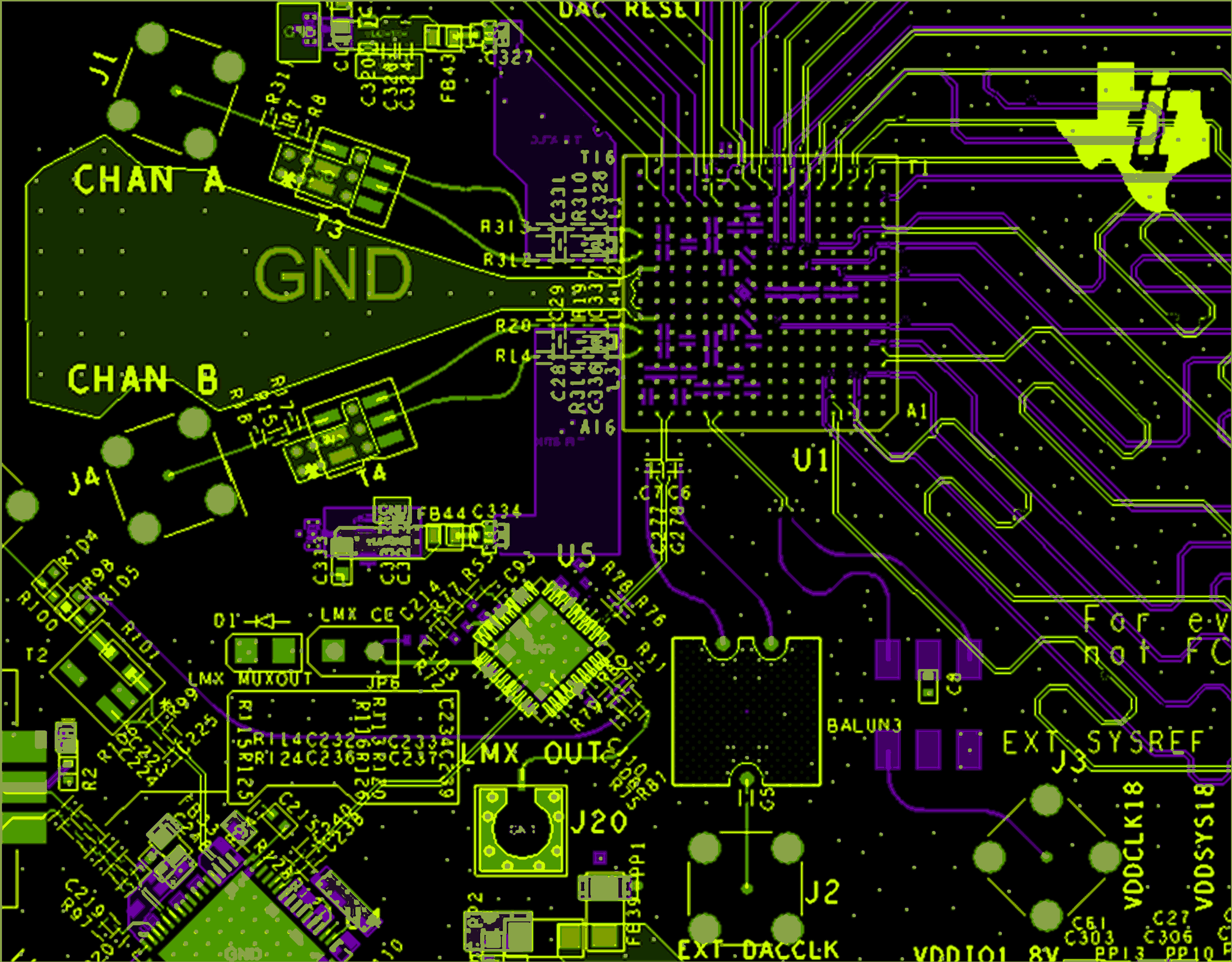
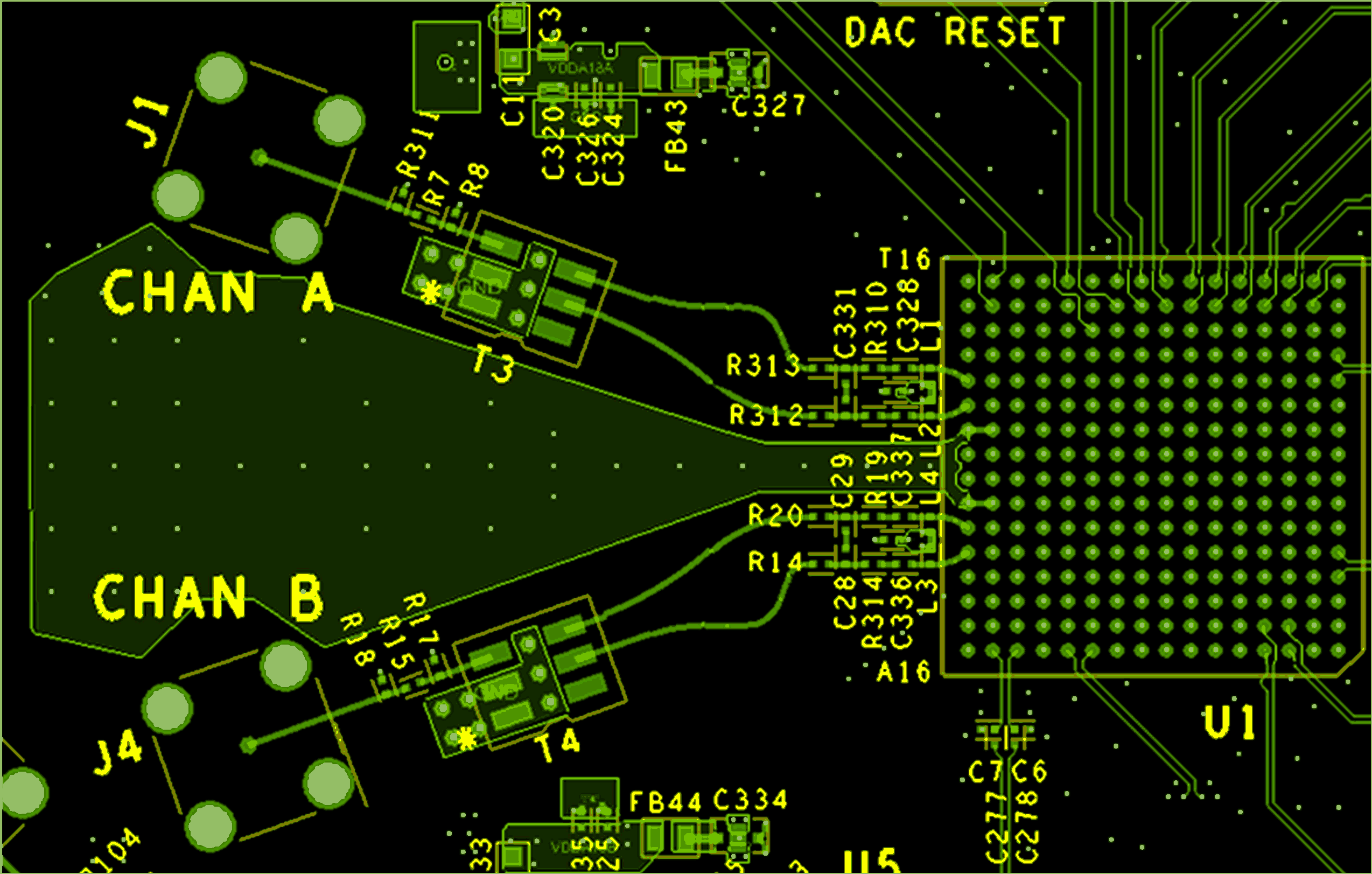
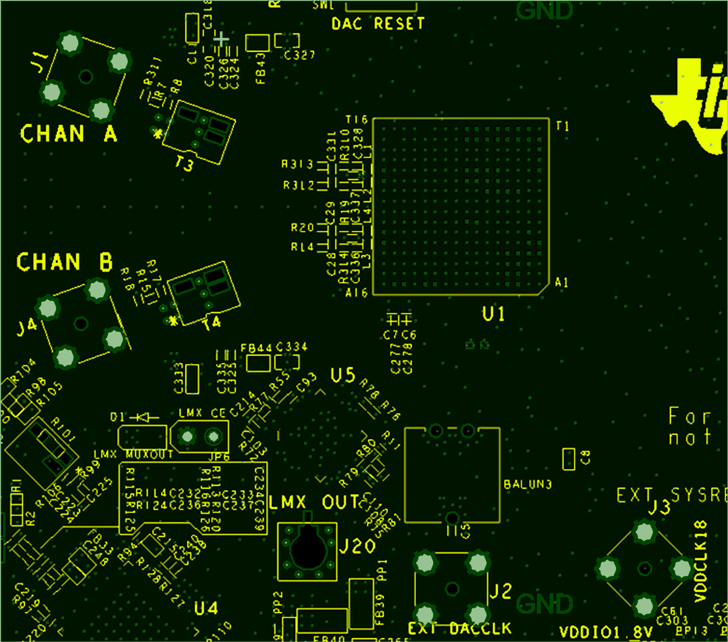
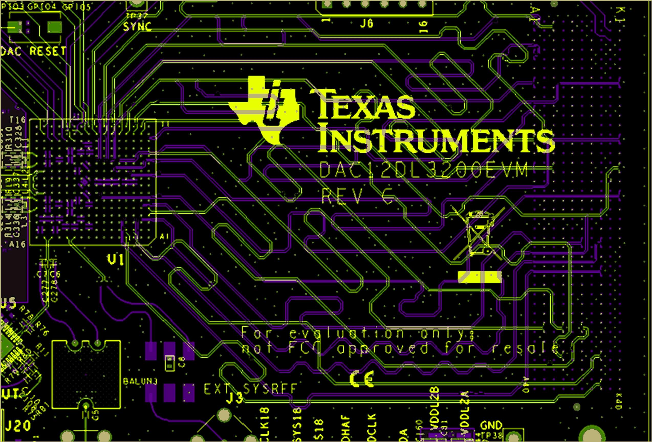
Figure 8-5 through Figure 8-8 provide examples of the critical traces routed on the device evaluation module (EVM).
 Figure 8-5 Top
(green traces) and Bottom (purple traces) Routing of DAC CLK and SYSREF
  Figure 8-6 DAC
Output Channels Routed on Top Layer
 Figure 8-7 PCB
cutouts under output transformers T3 and T4 on layers 2 thru 5.
  Figure 8-8 LVDS
input data routing on top and bottom layers