SDAA192 November 2025 UCC33020 , UCC33020-Q1 , UCC33410 , UCC33410-Q1 , UCC33420 , UCC33420-Q1
2.1 Setup
To avoid coupling of the H filed coming from the integrated transformer of UCC33xx0-Q1 to the LISN, it is recommended to have tightly coupled connections between the positive and the return of the switching loop. The switching loop starts at the 12V battery supply. The switching loop goes through the LISN, and the loop finally connects to the input of the DUT PCB. The following images show an example of tight connections for the whole switching loop for CE and RE.
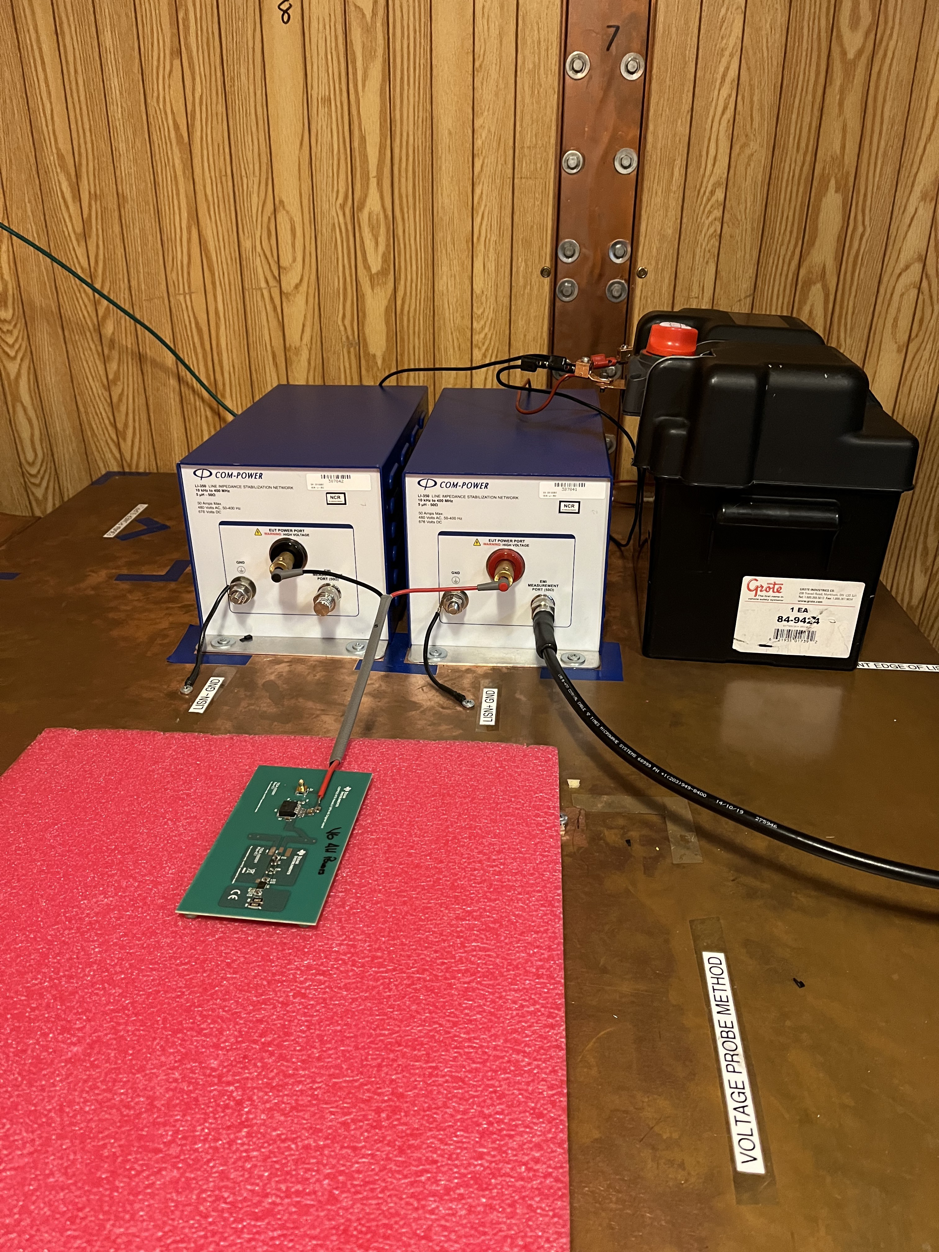 Figure 2-1 CISPR 25 CE Setup
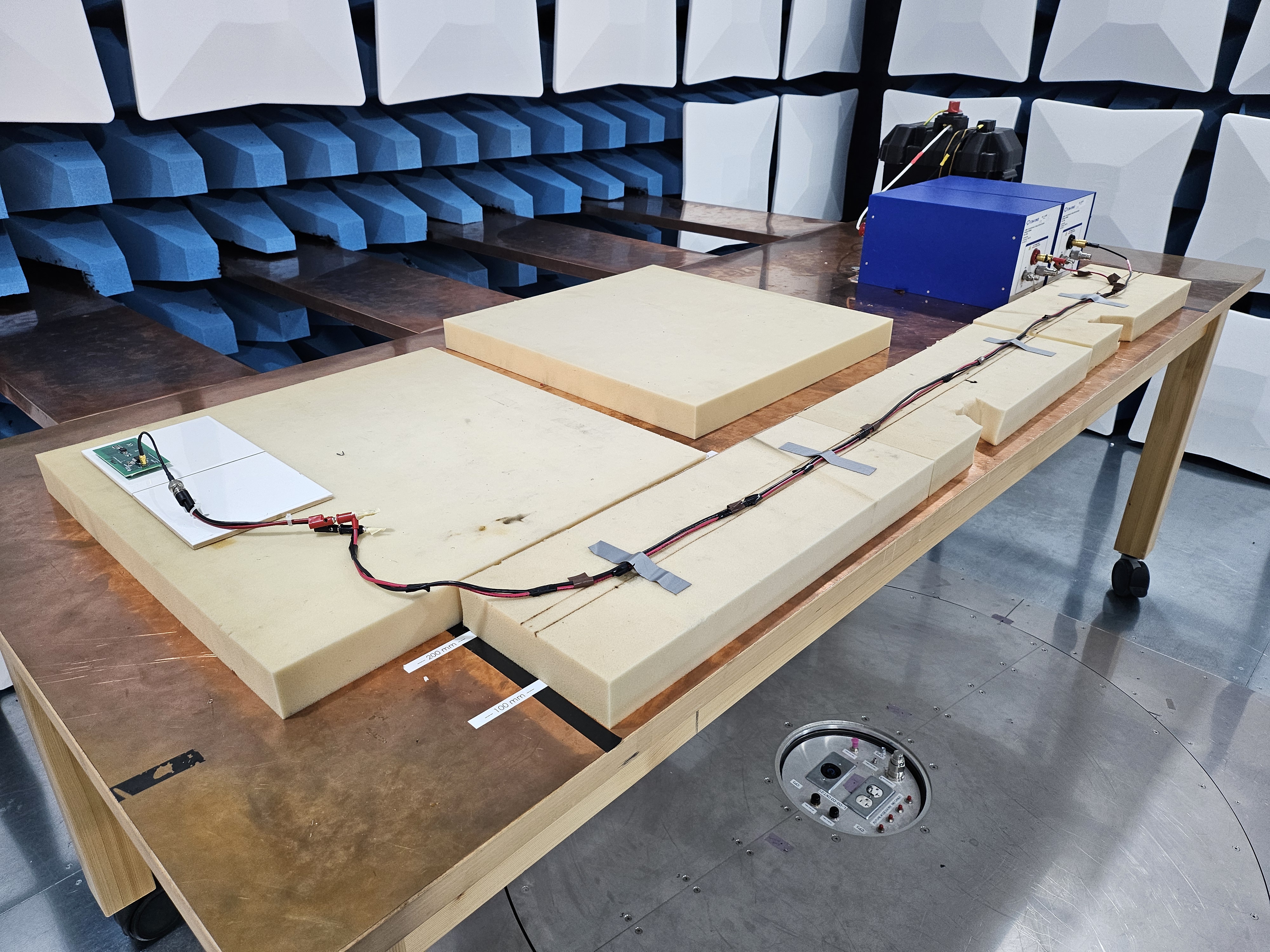 Figure 2-2 CISPR 25 RE Setup
Comparison between tightly coupled connection and open loop connection; the following images show the difference between tightly coupled and open loop connection for UCC33420-Q1 CE Pout=0.5W.
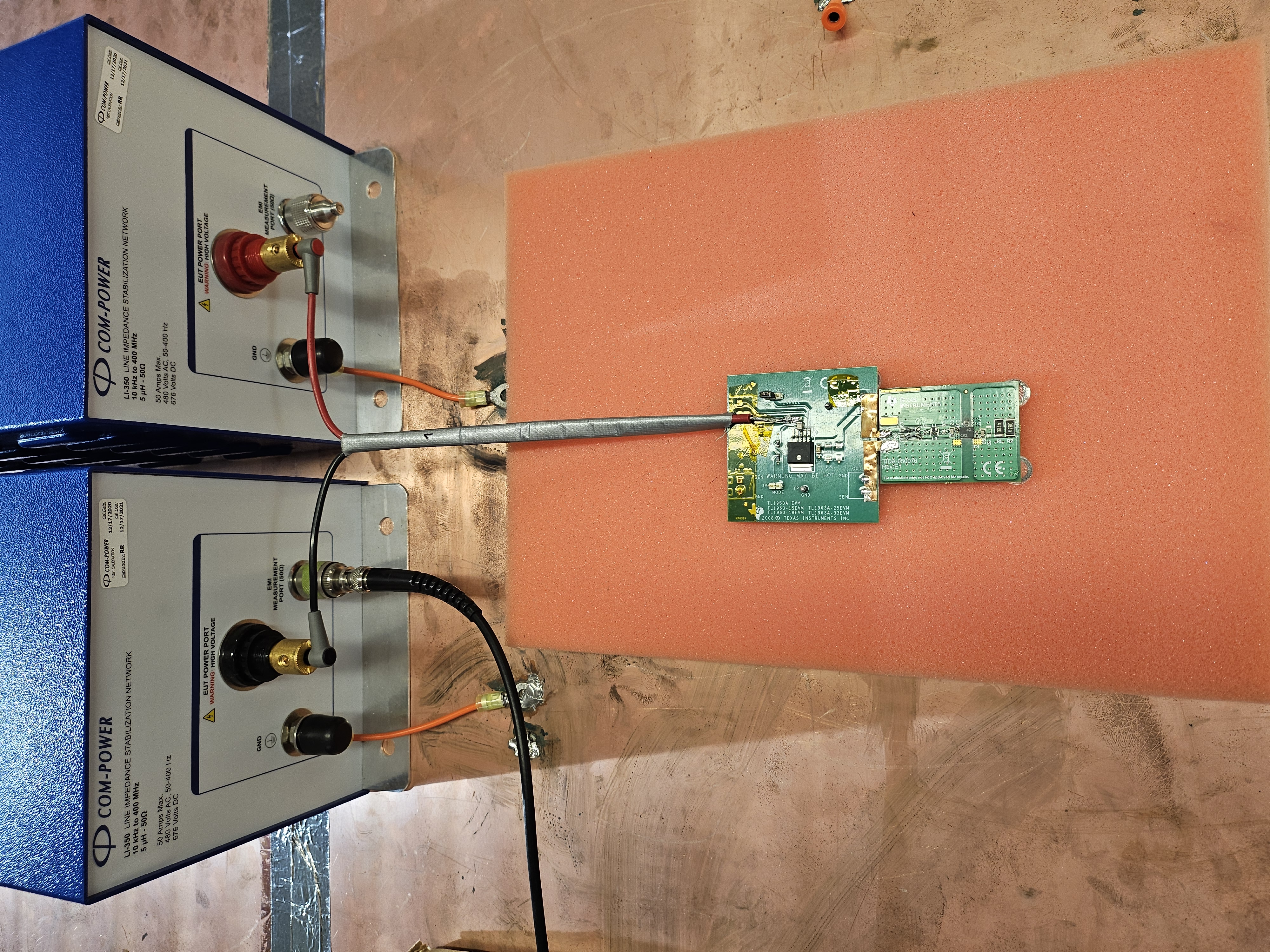 Figure 2-3 Tightly Coupled Leads
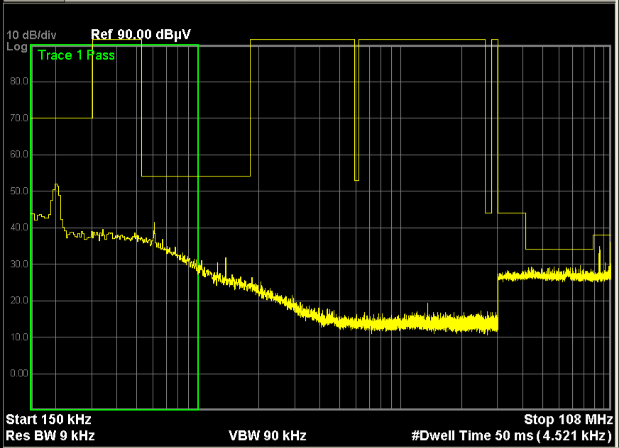 Figure 2-4 CISPR 25 CE Tightly Coupled Leads,
Pout=0.5W
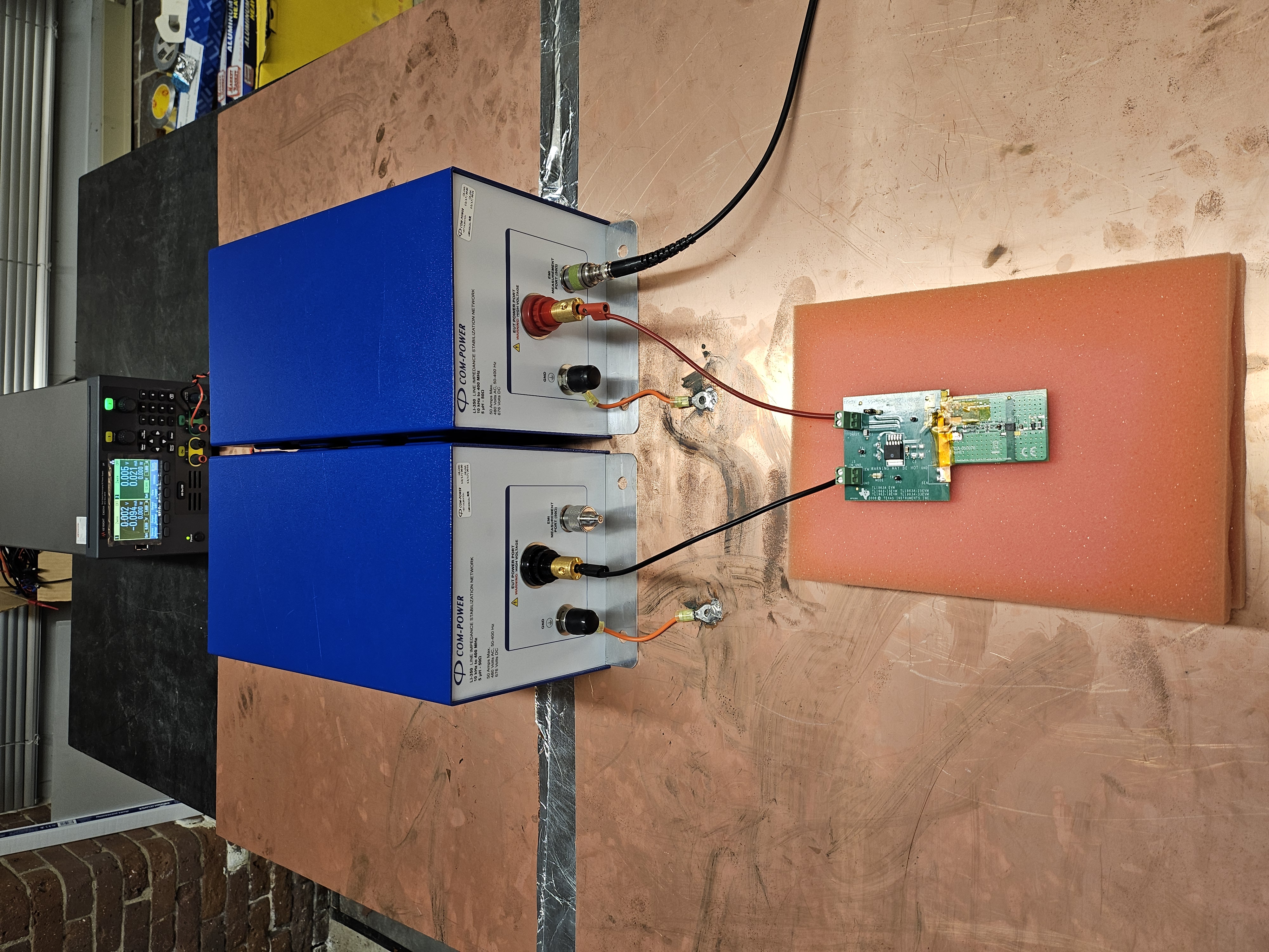 Figure 2-5 Opened Leads
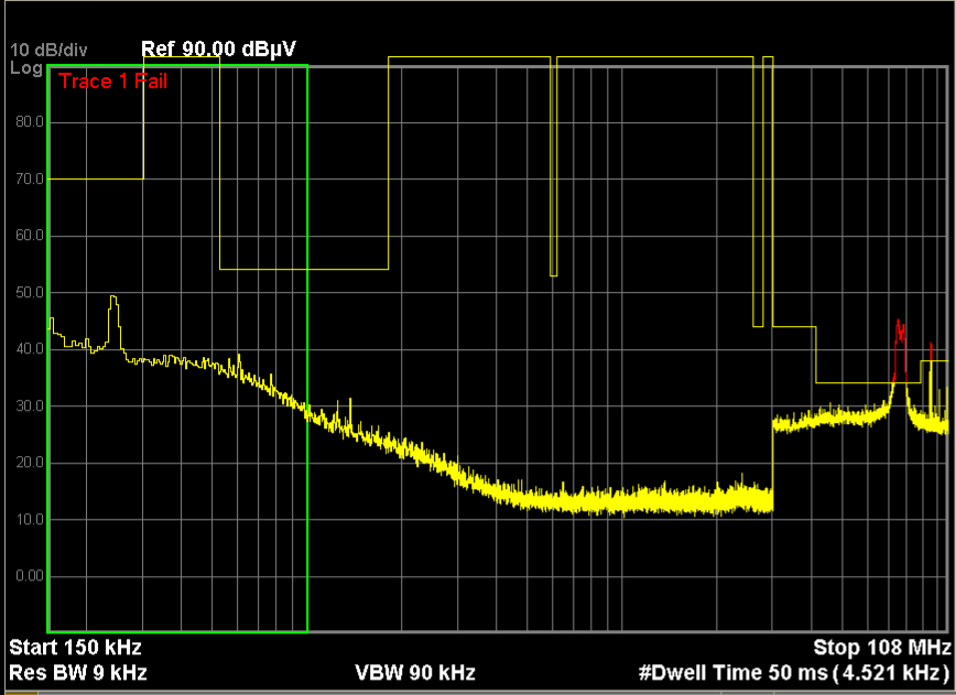 Figure 2-6 CISPR 25 CE Opened Leads,
Pout=0.5W