SDAA192 November 2025 UCC33020 , UCC33020-Q1 , UCC33410 , UCC33410-Q1 , UCC33420 , UCC33420-Q1
2.2 EMI Filter
To mitigate the noise coming from the switching frequency fsw=64MHz, we used a pi filter with a dual DM inductor (top and bottom). The reason of the dual inductor is the impedance match at the switching loop to avoid high CM noise. The selection of the inductor was done based on impedance vs. frequency plot, shielding, size and current rating. A 2.2uH with high SRF (self-resonant frequency) fully shielded 0806 molded inductor was selected. Table 2-1 shows the DM inductor selection by power level.
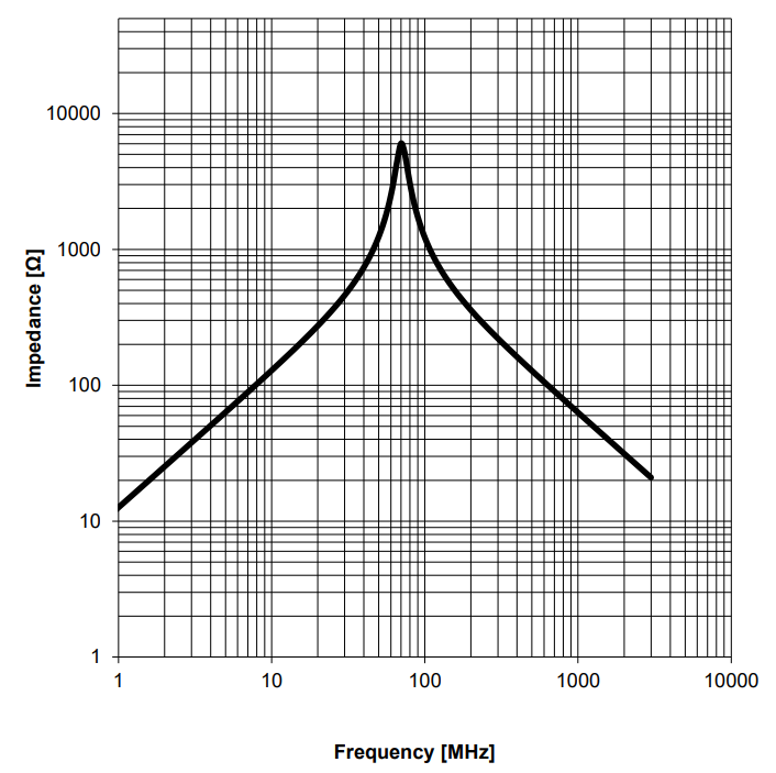 Figure 2-7 Impedance vs. Frequency - DM
Inductor
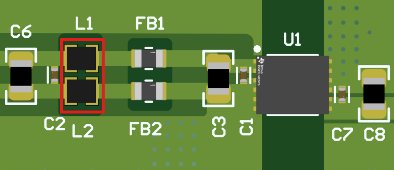 Figure 2-8 Dual DM Inductor in the PCB
| Power Level | DM Inductor |
|---|---|
| 0.5W | PN:74479763222; 2.2uH, 0603, 800mA |
| 1W | PN:74438343022; 2.2uH, 2mmx1.6mm, 1.65A |
An 0402 50V 15nF capacitor with high SRF was placed at the left side of the inductors. This capacitor was used to form the pi filter with the inductors and the 15nF connected next to the input pins.
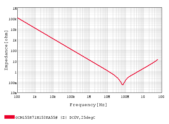 Figure 2-9 Impedance vs. Frequency - 0402
15nF
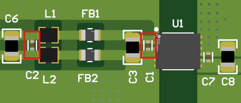 Figure 2-10 0402 15nF capacitors in the
PCB
Figure 2-10 0402 15nF capacitors in the
PCBFB are needed to mitigate the HF current harmonics that are present in the range of 200MHz-1GHz. 0603, 800mA ferrite beads with an impedance of 925 at 600MHz, fully shielded were selected to achieve low EMI at this range. These ferrite beads were placed next to the DUT for better H filed mitigation at high frequencies.
 Figure 2-11 Impedance vs. Frequency - FB
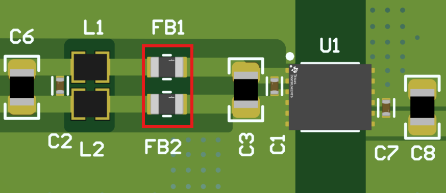 Figure 2-12 FB in the PCB
Comparison with and without FB: Figure 2-13 and Figure 2-14 show the comparison with and without FB for UCC33420-Q1 RE Pout=0.5W.
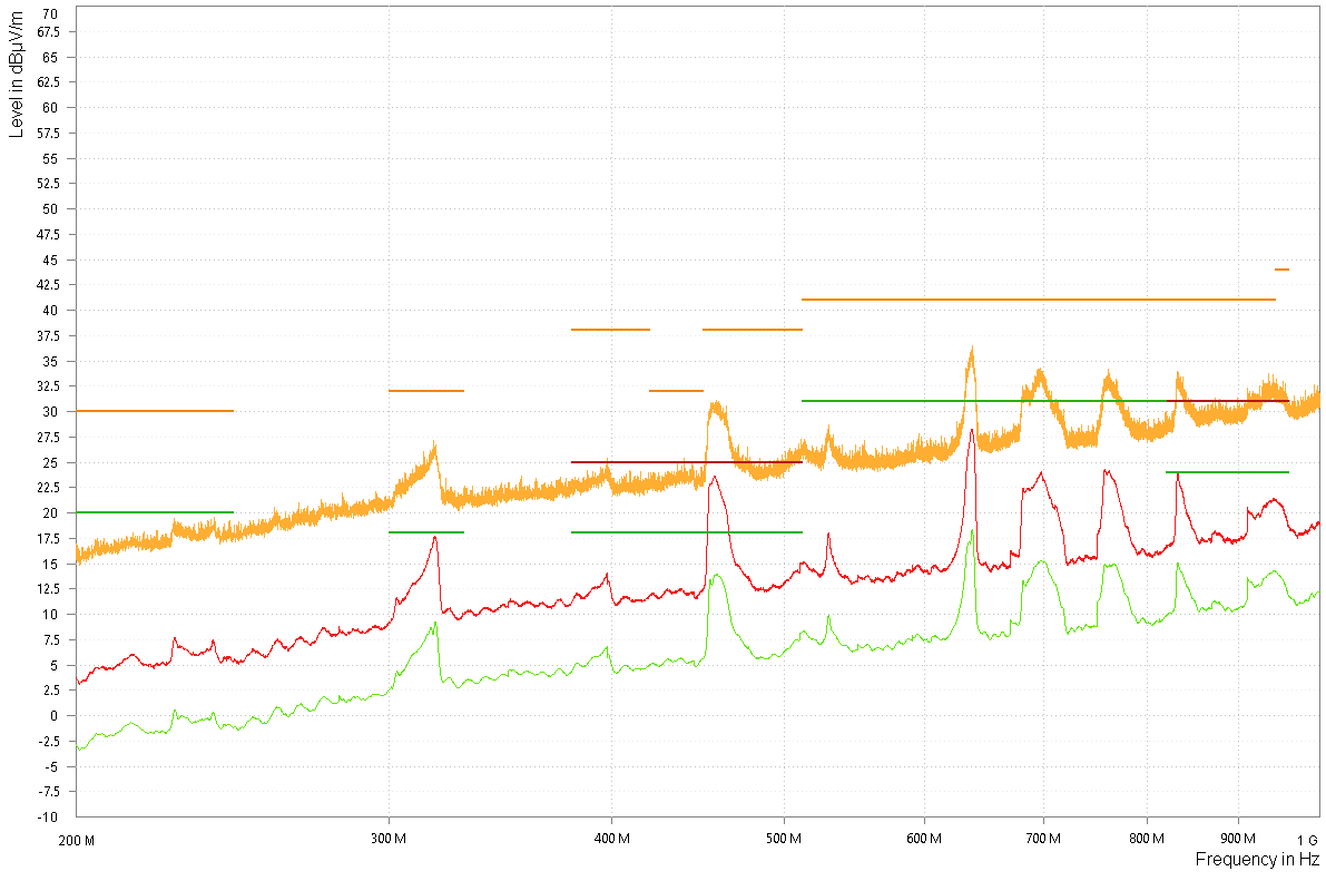 Figure 2-13 CISPR25 RE LPA with FB,
Pout=0.5W
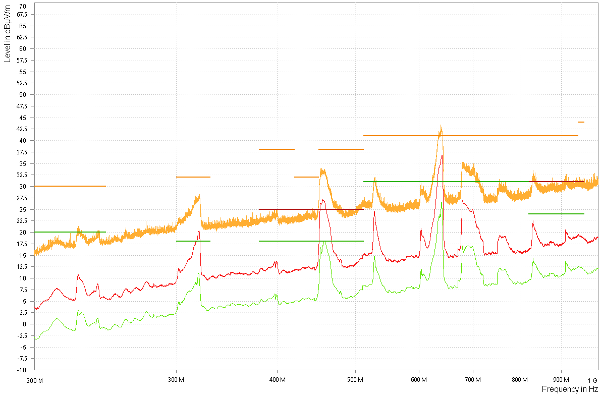 Figure 2-14 CISPR25 RE LPA without FB,
Pout=0.5W
Figure 2-14 CISPR25 RE LPA without FB,
Pout=0.5WFinally, an 0805 10uH bypass cap was placed at the left side of the switching loop to form a low frequency pi filter with the DM inductors and the 10uF bypass cap next to the input pins of the device. The target frequency is the burst frequency of the device which is in the range of 100-500kHz depending on the load.