SBOU192 July 2017
-
DIYAMP-SC70-EVM
- Trademarks
- 1 Introduction
- 2 Hardware Setup
- 3
Schematic and PCB Layout
- 3.1 Schematic PCB Drawing
- 3.2 Single-Supply, Multiple Feedback Filter
- 3.3 Single-Supply, Sallen-Key Filter
- 3.4 Single-Supply, Non-Inverting Amplifier
- 3.5 Single-Supply, Inverting Amplifier
- 3.6 Difference Amplifier
- 3.7 Dual-Supply, Multiple Feedback Filter
- 3.8 Dual-Supply, Sallen-Key Filter
- 3.9 Inverting Comparator
- 3.10 Non-Inverting Comparator
- 3.11 Riso With Dual Feedback
- 3.12 Dual-Supply, Non-Inverting Amplifier
- 3.13 Dual-Supply, Inverting Amplifier
- 4 Connections
- 5 Bill of Materials and Reference
4.1 Inputs and Outputs
The input/output connection slots were designed to fit the following connections: vertical SMA, horizontal SMA, wires, or through-hole test points. Examples of these four connectors are shown in this section.
The SMA recommended for this board is TE Connectivity part number 5-1814400-1.
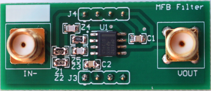
Figure 46 shows SMA vertical connectors attached to both the input and output terminal.
 Figure 46. SMA Vertical Connectors
 Figure 47 shows SMA horizontal connectors attached to the input signal terminal.
 Figure 47. SMA Horizontal Connectors
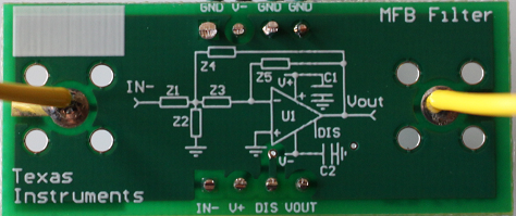
 Figure 48 shows a wire attached to the input and output terminal.
 Figure 48. Wire Connections
 Figure 49 shows a through-hole test point connector attached to the output and Vref terminal.
 Figure 49. Through-Hole Test Points
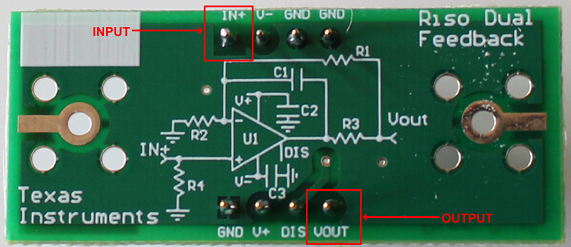
 The input and output connections can also be accessed from the header strip. The input connections are labeled IN+ and IN- for the non-inverting and inverting inputs, respectively. The output connection is labeled VOUT. An example highlighting the input and output is shown in Figure 50.
 Figure 50. Input and Output Pins in Terminal Area