SBOU192 July 2017
-
DIYAMP-SC70-EVM
- Trademarks
- 1 Introduction
- 2 Hardware Setup
- 3
Schematic and PCB Layout
- 3.1 Schematic PCB Drawing
- 3.2 Single-Supply, Multiple Feedback Filter
- 3.3 Single-Supply, Sallen-Key Filter
- 3.4 Single-Supply, Non-Inverting Amplifier
- 3.5 Single-Supply, Inverting Amplifier
- 3.6 Difference Amplifier
- 3.7 Dual-Supply, Multiple Feedback Filter
- 3.8 Dual-Supply, Sallen-Key Filter
- 3.9 Inverting Comparator
- 3.10 Non-Inverting Comparator
- 3.11 Riso With Dual Feedback
- 3.12 Dual-Supply, Non-Inverting Amplifier
- 3.13 Dual-Supply, Inverting Amplifier
- 4 Connections
- 5 Bill of Materials and Reference
2.1 EVM Circuit Locations
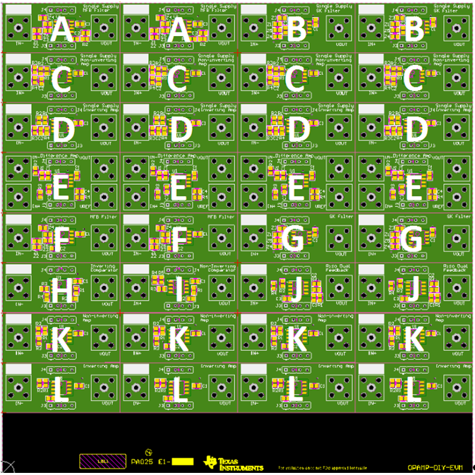
Figure 1 and Table 2 map the location of each circuit configuration on the EVM. Figure 1 labels each circuit configuration with a letter ranging from A to L. Table 2 matches the circuit configuration to a letter in Figure 1 and also provides the name of each individual circuit written in silk screen on the EVM.
 Figure 1. Location of Circuit Configurations
 Table 2. Location of Circuit Legend
| Circuit Name | Silk Screen Label | Letter in Figure 1 |
|---|---|---|
| Single-supply multiple feedback filter | Single-Supply MFB Filter | A |
| Single-supply Sallen Key filter | Single-Supply SK Filter | B |
| Single-supply non-inverting amplifier | Single-Supply Non-Inverting Amp | C |
| Single-supply inverting amplifier | Single-Supply Inverting Amp | D |
| Difference amplifier | Difference Amp | E |
| Dual-supply multiple feedback filter | MFB Filter | F |
| Dual-supply Sallen Key filter | SK Filter | G |
| Inverting comparator | Inverting Comparator | H |
| Non-inverting comparator | Non-Inverting Comparator | I |
| Riso with dual feedback | Riso Dual Feedback | J |
| Dual-supply non-inverting amplifier | Non-Inverting Amp | K |
| Dual-supply inverting amplifier | Inverting Amp | L |