ZHCSLS7A December 2020 – January 2022 LMK1C1106 , LMK1C1108
PRODUCTION DATA
- 1 特性
- 2 應(yīng)用
- 3 說明
- 4 Revision History
- 5 Pin Configuration and Functions
- 6 Specifications
- 7 Parameter Measurement Information
- 8 Detailed Description
- 9 Application and Implementation
- 10Power Supply Recommendations
- 11Layout
- 12Device and Documentation Support
- 13Mechanical, Packaging, and Orderable Information
封裝選項
機(jī)械數(shù)據(jù) (封裝 | 引腳)
- PW|16
散熱焊盤機(jī)械數(shù)據(jù) (封裝 | 引腳)
訂購信息
5 Pin Configuration and Functions
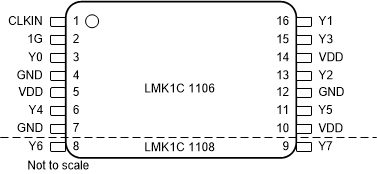
 Figure 5-1 LMK1C1106 and LMK1C1108 PW Package14-Pin TSSOP and 16-Pin TSSOPTop View
Table 5-1 Pin Functions
| PIN | TYPE | DESCRIPTION | ||
|---|---|---|---|---|
| NAME | LMK1C 1106 |
LMK1C 1108 |
||
| LVCMOS CLOCK INPUT | ||||
| CLKIN | 1 | 1 | Input | Single-ended clock input with internal 300-kΩ (typical) pulldown resistor to GND. Typically connected to a single-ended clock input. |
| CLOCK OUTPUT ENABLE | ||||
| 1G | 2 | 2 | Input | Global Output Enable with internal 300-k? (typical) pulldown resistor
to GND. Typically connected to VDD with external pullup resistor. HIGH: outputs enabled LOW: outputs disabled |
| LVCMOS CLOCK OUTPUT | ||||
| Y0 | 3 | 3 | Output | LVCMOS output. Typically connected to a receiver. Unused outputs can be left floating. |
| Y1 | 14 | 16 | ||
| Y2 | 11 | 13 | ||
| Y3 | 13 | 15 | ||
| Y4 | 6 | 6 | ||
| Y5 | 9 | 11 | ||
| Y6 | – | 8 | ||
| Y7 | – | 9 | ||
| SUPPLY VOLTAGE | ||||
| VDD | 5 | 5 | Power | Power supply terminal. Typically connected to a 3.3-V, 2.5-V, or 1.8-V supply. The VDD pin is typically connected to an external 0.1-μF capacitor near the pin. |
| 8 | 10 | |||
| 12 | 14 | |||
| GROUND | ||||
| GND | 4 | 4 | GND | Device ground. |
| 7 | 7 | |||
| 10 | 12 | |||