SLUP408 February 2022 LM25149-Q1 , LM61460-Q1 , LM61495-Q1 , LMQ61460-Q1
- 1 Introduction
- 2 Defining EMI
- 3 What Causes EMI in a Switched-Mode DC/DC Regulator?
- 4 Existing Passive EMI Filtering Techniques
- 5 Passive Filter Limitations
- 6 AEF
- 7 Spread Spectrum
- 8 DRSS
- 9 True Slew-Rate Control
- 10HotRod? Package Technology
- 11Optimized Package and Pinout
- 12Integrated Capacitors
- 13Conclusions
- 14References
- 15Important Notice
12 Integrated Capacitors
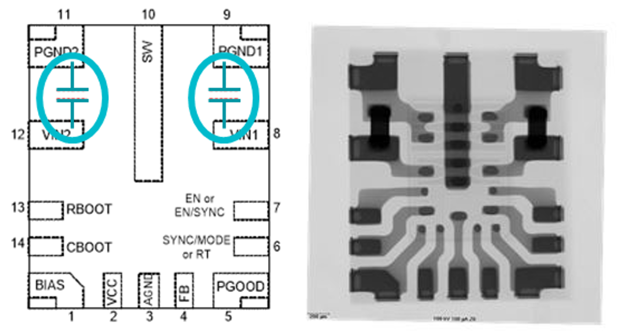
The input current loop is a high di/dt loop that affects EMI at higher frequency ranges. Devices that integrate a high-frequency input decoupling capacitor effectively reduce the high di/dt inductive loop area and help further reduce EMI.
Figure 12-1 provides an example of a device with integrated capacitors. These integrated capacitors are soldered directly onto the internal leadframe of the device, which minimizes the parasitic inductance on the input loop.
 Figure 12-1 Integrated capacitors in the
LMQ61460-Q1.
Figure 12-1 Integrated capacitors in the
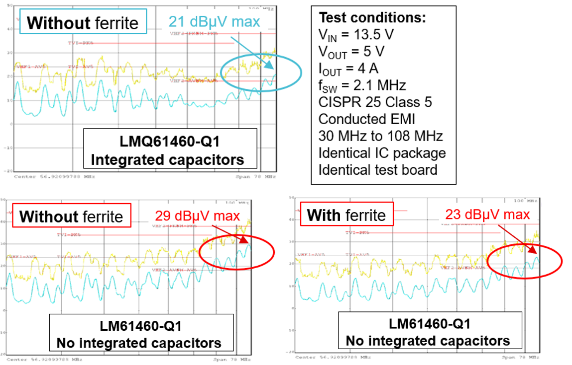
LMQ61460-Q1.The lab EMI measurements shown in Figure 12-2 demonstrate that, without an input ferrite bead, a device with an integrated capacitor provides approximately 8 dBμV of margin compared to a device without an integrated capacitor. When comparing a device with an integrated capacitor to a device without an integrated capacitor – but with an input ferrite bead – the device with the integrated capacitor provides an approximate 2- to 3-dBμV improvement.
 Figure 12-2 EMI comparisons between the
LM61460-Q1 and LMQ61460-Q1 automotive buck converters.
Figure 12-2 EMI comparisons between the
LM61460-Q1 and LMQ61460-Q1 automotive buck converters.The LMQ61460-Q1 and LM62440-Q1 step-down converters use this device package construction method. Integrating the input decoupling capacitors inside the device provides a solution that is resistant to EMI and easy to lay out.
As shown in Figure 12-3, a device with integrated input decoupling capacitors lowers EMI and offers more margin without the need for slew-rate control compared to a device using only slew-rate control and no integrated capacitors. By combining the HotRod package with integrated capacitors, the LMQ61460-Q1 aims to attenuate high-frequency noise at the input path. Any additional device features to help attenuate EMI noise such as true slew-rate control add to a more reliable EMI design.
 Figure 12-3 EMI comparisons between the
LM61460-Q1 with slew-rate control and the LMQ61460-Q1.