SCDK004A June 2024 – November 2024 TMUX582F-SEP
PRODUCTION DATA
2.3.1 Bias Diagrams
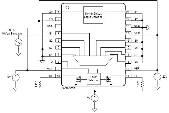
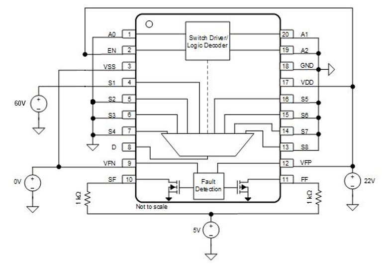
Figure 2-1 shows the bias conditions for each pin during the standard HDR and LDR characterization. Figure 2-2 shows the bias conditions for each pin during the 22V RLAT characterization at 30krad. Figure 2-3 shows the bias conditions for each pin during a 60V fault condition.
 Figure 2-1 TMUX582F-SEP Biased Diagram for Main HDR/LDR Characterization
![TMUX582F-SEP TMUX582F-SEP Biased Diagram for 22V S1 Pin Stress [RLAT] TMUX582F-SEP TMUX582F-SEP Biased Diagram for 22V S1 Pin Stress [RLAT]](/ods/images/SCDK004A/GUID-20241010-SS0I-GVR3-Z7Y4-4JTOCQ60IPFI-low.png) Figure 2-2 TMUX582F-SEP Biased Diagram for 22V S1 Pin Stress [RLAT]
Figure 2-2 TMUX582F-SEP Biased Diagram for 22V S1 Pin Stress [RLAT] Figure 2-3 TMUX582F-SEP Biased Diagram for 60V S1 Pin Stress