ZHCSBQ9C October 2013 – January 2021 TPS62085 , TPS62086 , TPS62087
PRODUCTION DATA
- 1 特性
- 2 應(yīng)用
- 3 說明
- 4 Revision History
- 5 Device Options
- 6 Pin Configuration and Functions
- 7 Specifications
- 8 Detailed Description
- 9 Application and Implementation
- 10Power Supply Recommendations
- 11Layout
- 12Device and Documentation Support
封裝選項(xiàng)
機(jī)械數(shù)據(jù) (封裝 | 引腳)
- RLT|7
散熱焊盤機(jī)械數(shù)據(jù) (封裝 | 引腳)
訂購(gòu)信息
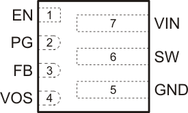
6 Pin Configuration and Functions
 Figure 6-1
RLT Package
7-Pin VSON
Top View
Table 6-1 Pin Functions
| PIN | I/O | DESCRIPTION | |
|---|---|---|---|
| NAME | NO. | ||
| EN | 1 | IN | Device enable pin. To enable the device, this pin needs to be pulled high. Pulling this pin low disables the device. This pin has a pulldown resistor of typically 400 kΩ when the device is disabled. |
| FB | 3 | IN | Feedback pin. For the fixed output voltage versions this pin must be connected to the output voltage. |
| GND | 5 | Ground pin. | |
| PG | 2 | OUT | Power good open drain output pin. The pullup resistor can not be connected to any voltage higher than 6 V. If unused, leave it floating. |
| SW | 6 | PWR | Switch pin of the power stage. |
| VIN | 7 | PWR | Input voltage pin. |
| VOS | 4 | IN | Output voltage sense pin. This pin must be directly connected to the output capacitor. |