ZHCS002E March 2007 – December 2014 TPS61200 , TPS61201 , TPS61202
PRODUCTION DATA.
- 1 特性
- 2 應(yīng)用范圍
- 3 說(shuō)明
- 4 典型應(yīng)用
- 5 修訂歷史記錄
- 6 Device Options
- 7 Pin Configuration and Functions
- 8 Specifications
- 9 Parameter Measurement Information
- 10Detailed Description
- 11Application and Implementation
- 12Power Supply Recommendations
- 13Layout
- 14器件和文檔支持
- 15機(jī)械、封裝和可訂購(gòu)信息
封裝選項(xiàng)
機(jī)械數(shù)據(jù) (封裝 | 引腳)
- DRC|10
散熱焊盤(pán)機(jī)械數(shù)據(jù) (封裝 | 引腳)
- DRC|10
訂購(gòu)信息
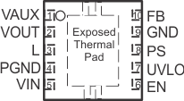
7 Pin Configuration and Functions
DSC and DRC Package
10 Pins
Top View
