SNAS624B March 2014 – May 2015 LMX2492 , LMX2492-Q1
PRODUCTION DATA.
- 1 Features
- 2 Applications
- 3 Description
- 4 Simplified Schematic
- 5 Revision History
- 6 Pin Configuration and Functions
- 7 Specifications
-
8 Detailed Description
- 8.1 Overview
- 8.2 Functional Block Diagram
- 8.3
Feature Description
- 8.3.1 OSCin Input
- 8.3.2 OSCin Doubler
- 8.3.3 R Divider
- 8.3.4 PLL N Divider
- 8.3.5 Fractional Circuitry
- 8.3.6 PLL Phase Detector and Charge Pump
- 8.3.7 External Loop Filter
- 8.3.8 Fastlock and Cycle Slip Reduction
- 8.3.9 Lock Detect and Charge Pump Voltage Monitor
- 8.3.10 FSK/PSK Modulation
- 8.3.11 Ramping Functions
- 8.3.12 Power on Reset (POR)
- 8.4 Device Functional Modes
- 8.5 Programming
- 8.6 Register Map
- 8.7 Register Field Descriptions
- 8.8 Lock Detect and Charge Pump Monitoring
- 8.9 TRIG1,TRIG2,MOD, and MUXout Pins
- 8.10 Ramping Functions
- 8.11 Individual Ramp Controls
- 9 Applications and Implementation
- 10Power Supply Recommendations
- 11Layout
- 12Device and Documentation Support
- 13Mechanical, Packaging, and Orderable Information
封裝選項
機械數(shù)據(jù) (封裝 | 引腳)
- RTW|24
散熱焊盤機械數(shù)據(jù) (封裝 | 引腳)
- RTW|24
訂購信息
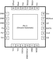
6 Pin Configuration and Functions
24 Pin WQFN
RTW Package
(Top View)
