SNOS739E July 1997 – November 2025 LMC6762
PRODUCTION DATA
- 1
- 1 FEATURES
- 2 APPLICATIONS
- 3 DESCRIPTION
- 4 Electrostatic Discharge Caution
- 5 Absolute Maximum Ratings #GUID-F10E56BA-F805-4EB7-A2D2-0BF8E26DF15C/SNOS7392194 #GUID-F10E56BA-F805-4EB7-A2D2-0BF8E26DF15C/SNOS7394381
- 6 Operating Ratings #GUID-2904839E-20BA-4119-B36D-EECFE39579F2/SNOS7390787
- 7 2.7V Electrical Characteristics
- 8 5.0V and 15.0V Electrical Characteristics
- 9 AC Electrical Characteristics
- 10Typical Characteristics
- 11Application Hints
- 12Revision History
11.6.4 Oscillator
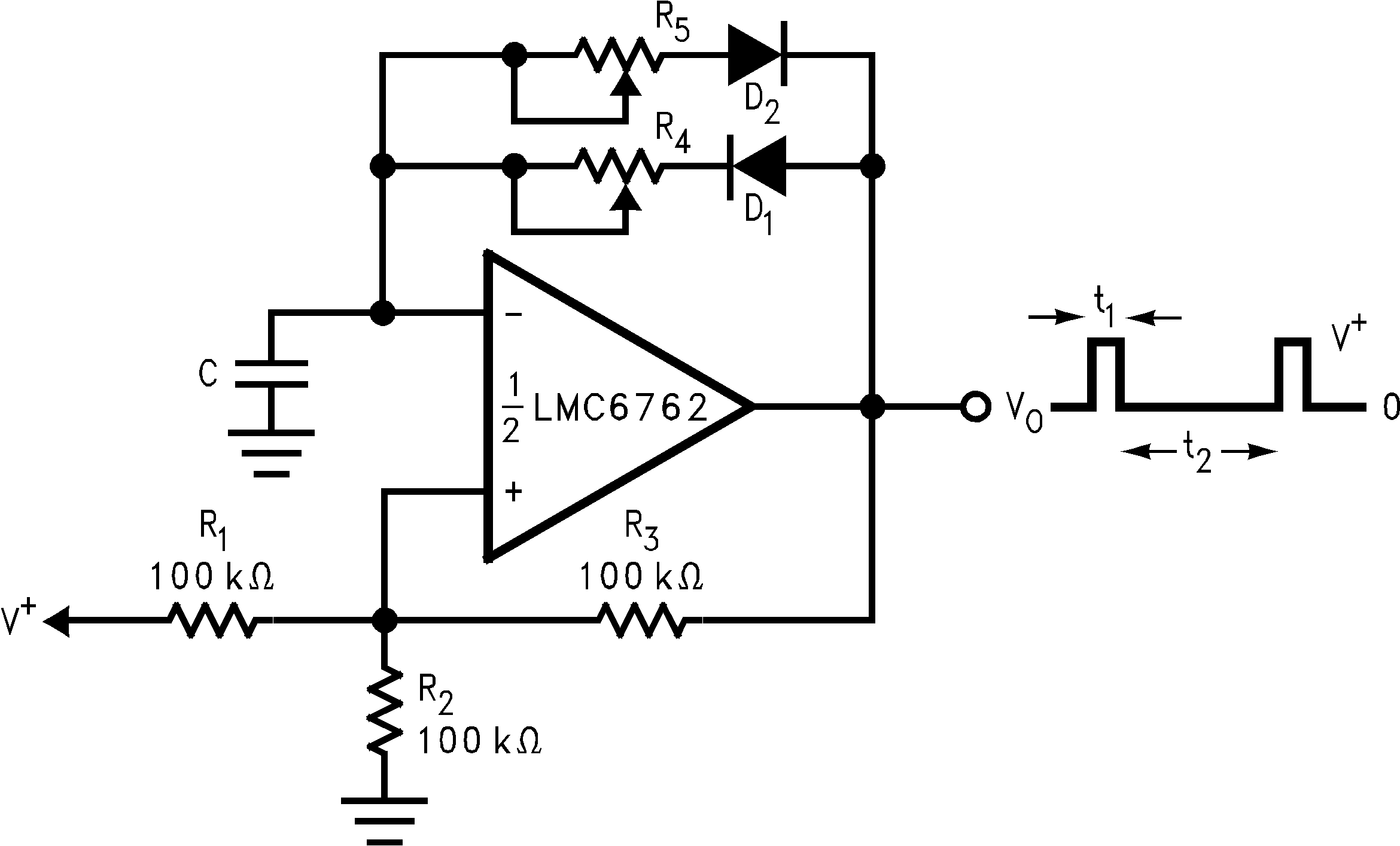
 Figure 11-7 Square Wave Generator
Figure 11-7 shows the application of the LMC6762 in a square wave generator circuit. The total hysteresis of the loop is set by R1, R2 and R3. R4 and R5 provide separate charge and discharge paths for the capacitor C. The charge path is set through R4 and D1. So, the pulse width t1 is determined by the RC time constant of R4 and C. Similarly, the discharge path for the capacitor is set by R5 and D2. Thus, the time t2 between the pulses can be changed by varying R5, and the pulse width can be altered by R4. The frequency of the output can be changed by varying both R4 and R5.
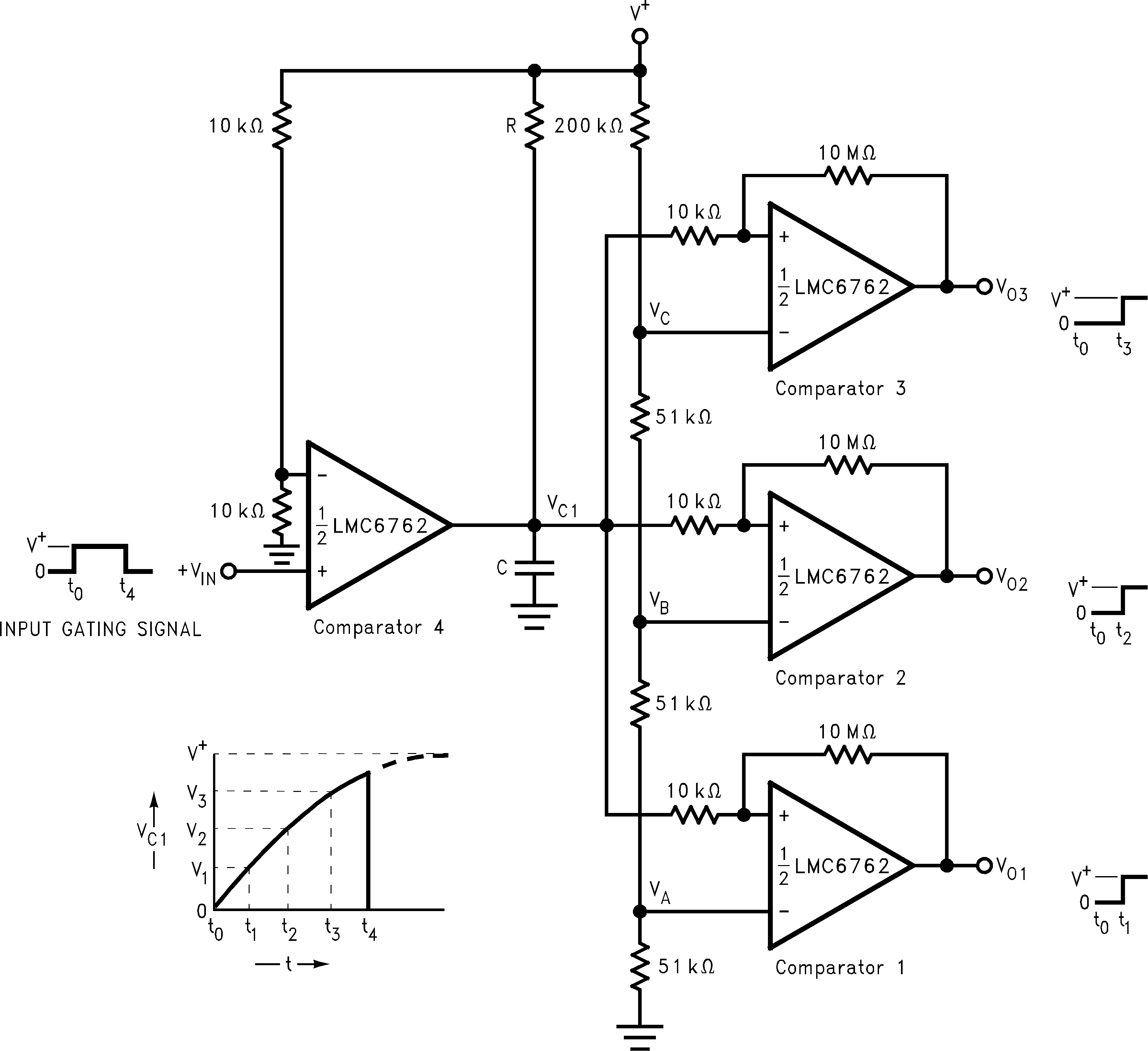
 Figure 11-8 Time Delay Generator
The circuit shown above provides output signals at a prescribed time interval from a time reference and automatically resets the output when the input returns to ground. Consider the case of VIN = 0. The output of comparator 4 is also at ground. This implies that the outputs of comparators 1, 2, and 3 are also at ground. When an input signal is applied, the output of comparator 4 swings high and C charges exponentially through R. This is indicated above.
The output voltages of comparators 1, 2, and 3 switch to the high state when VC1 rises above the reference voltage VA, VB and VC. A small amount of hysteresis has been provided to insure fast switching when the RC time constant is chosen to give long delay times.